"Eliminator" sport jet - Past project
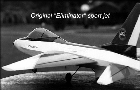
In 1992, I decided to design and kit a prop jet, powered by a typical .45-size to .60-size engine, with a look something like an F-16. I had been looking at and studying plug and mold making, and was convinced that I could mold the fuselage from fiberglass, and use balsa-sheeted foam cores for the flying parts. The tech support team at Fibreglast, Inc., were a LOT of help to me, and talked me through the process before I began.
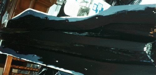
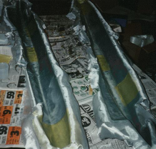
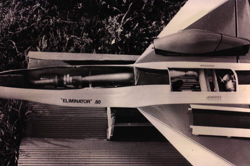
Sorry about the quality of this photo. It wasn't too good to begin with, and it's ancient.
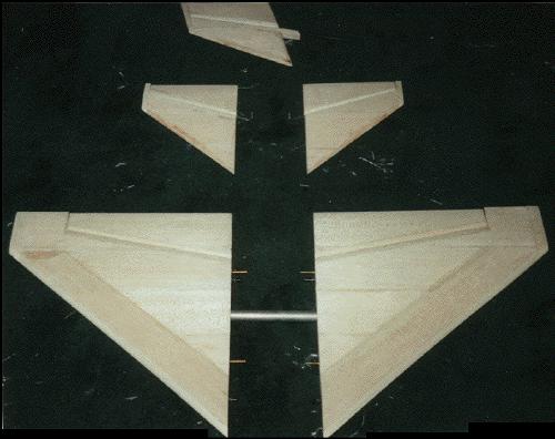
In order to make the fuselage plug properly, I had to have the flying surfaces finished first. So, I made templates for foam wing cores, sheeted them, and made sure they were right. Errors here would've affected the shape of the fuselage plug, so these parts were critical.
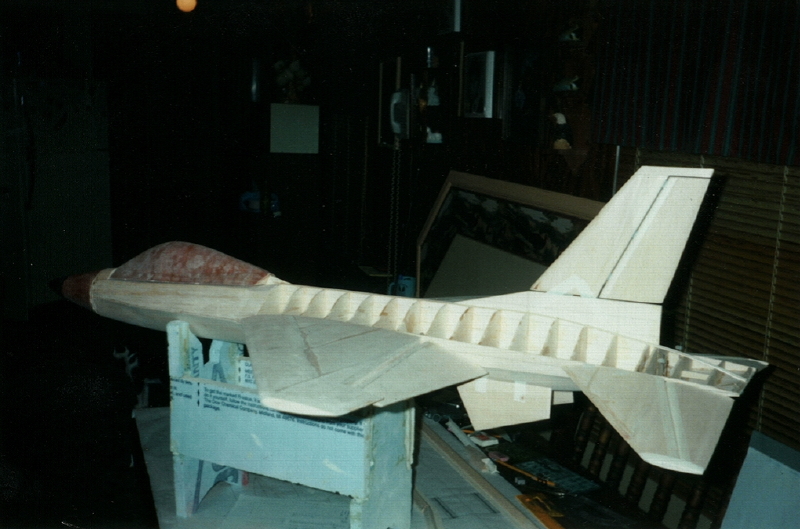
Following that, I cut out a keel and about 25 formers, and built the fuselage, which was sheeted and planked in a traditional way. Weight doesn't matter, when building a plug, so I was able to use whatever fillers and parts I needed to stiffen the structure, with no worries. You'll notice in the photo below that I built in a twist in the fuselage sides (like the actual F-16) to accommodate the anhedral tail parts. The canopy plug was built as a separate, removable part, made from a floor, keel, formers, foam, and finally covered with an epoxy.micro-balloons mixture that could be easily shaped.
I used the same connection types to attach the wing and tail parts to the plug that I would ultimately use on the finished airplane, so I was able to create indentations in the plugs, denoting where the wing tube and alignment pins would go. You can see them in the photos below. That makes alignment issues much simpler for the builder, later.
When I was happy with the shape of the fuselage and canopy parts, they were given a coat of what was then called "Akemi", a VERY tough tooling resin. That completely stabilized the parts, and enabled me to produce a close-to-mold-ready finish on them. The final step was to give them a generous coat of K&B epoxy primer, which was then buffed out, prior to making the molds.
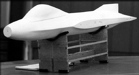
The fuselage and canopy plug, mated
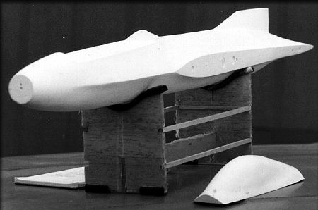
The same parts, separated.
The scariest part of the mold-making process was when I finally had to coat my beautiful plugs with tooling resin, which would become the inside surface of the female molds. If you do this, make SURE that you've waxed the parts and buffed them thoroughly, and that you've applied mold release per the manufacturer's instructions, or your plug will be forever locked into the mold. (!) Mine came out without any problems, which was great.
Making the molds begins...
I made the first fuselage from standard fiberglass, with a little Kevlar around the nose and the wing support area, for added rigidity. (the gold-colored material in the photo below) It was amazing to me how much this helped in both rigidity and overall strength, for almost zero weight penalty.. You'll notice that I've used a Dremel tool to grind away some parts of the fuselage mold where the (separately-molded) hatches would eventually go. This helps during the layup process, giving you greater access to check your work, once the mold halves are joined.
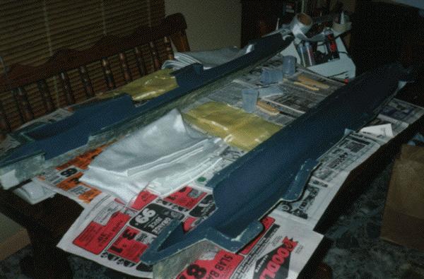
All the components for making the first fuselage, laid out.
The first fuselage layup.
The first layup went well, and the part was strong, yet light. I could've made it look better, but , being worried about the cloth weave showing, had added some micro-balloons to the mixture. This is an unnecessary step, which I never did again. No harm done... It just looks "cloudy".
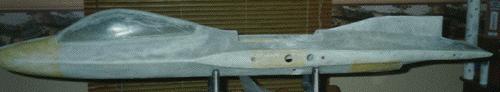
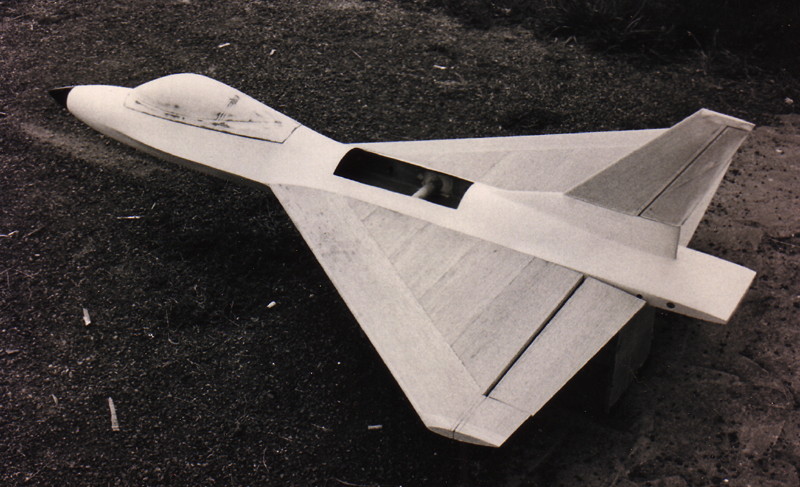
The first fuselage, out of the mold
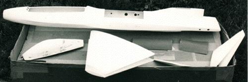
The "kit", ready to be assembled.
After the landing gear installation, a little primer and paint
The "antenna" you see just behind the canopy is a disguise for the handle of the BVM hatch latch.
The fuselage had a molded fiberglass tube running through it, into which a 1-inch aluminum tube rested. The aluminum tube then inserted into the carbon wing tube sockets in the wings, and used alignment pins to keep the angle correct. A simple nylon wing bolt, inserted from inside the fuselage, screwed into a threaded block in the wing and tail parts, holding them in place. (See photo below)
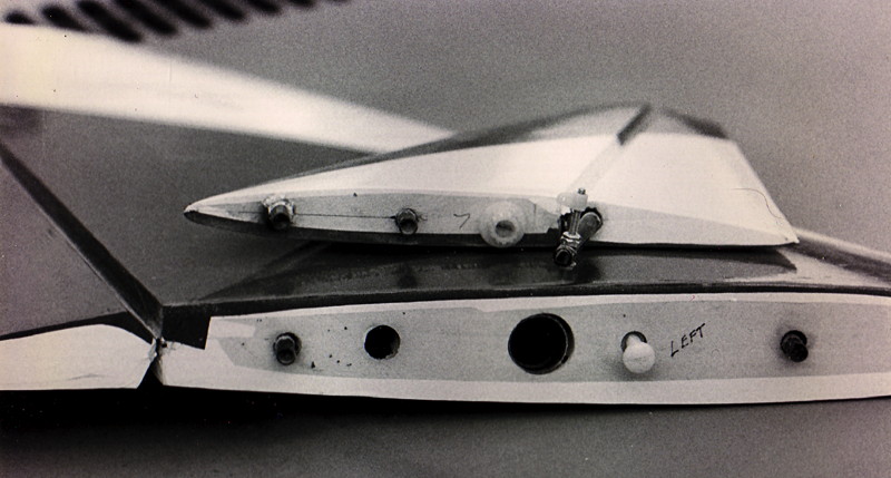
Alignment pins and bolt holes on the wing and tail parts.
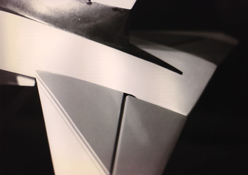
Here's a close-up of the anhedral tail parts in place.
I used Spring Air retracts in this plane, and the installation was both simple and strong. If you've never used Spring Air retracts, keep your fingers out of the way when testing them. They "slam" up very positively. (!)
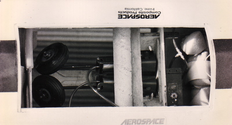
The Spring Air retracts, in the up position.
I had a YS .61 long stroke engine available, so decided to use it on the prototype, for more power. The tuned pipe was enclosed inside the fuselage, with the exhaust exiting through a diverter, in the landing gear area. (No gear doors were used on the prototype.) To be sure I didn't get anything too hot, I siliconed a piece of large fuel tubing into a recess carved in the supporting former. This worked fine... No problems.
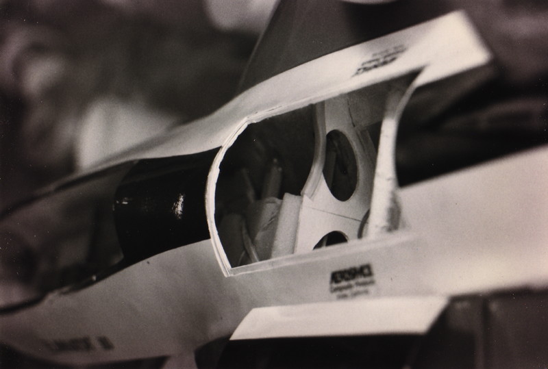
Insulating the former for the tuned pipe.
Here's the rather tight engine/pipe installation.
I was nervous, since this was my "first", in several categories... It was my first molded project, my second original design "jet" type, and like anyone, I hoped that all my "math" had been done right, during the design stage. I tested everything I could test on the ground, many times. Finally, there were no more excuses, and it was time to fly.
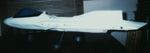
Ready to fly!
This model had a 48-inch wingspan, and a 60-inch length. To give you an idea of just how compact this is, I talked a modeler friend's wife into posing with the model, before I flew it.
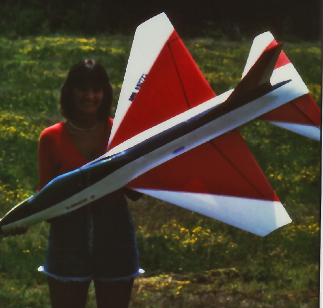
Ready to fly!
I should've stuck to my original plan...
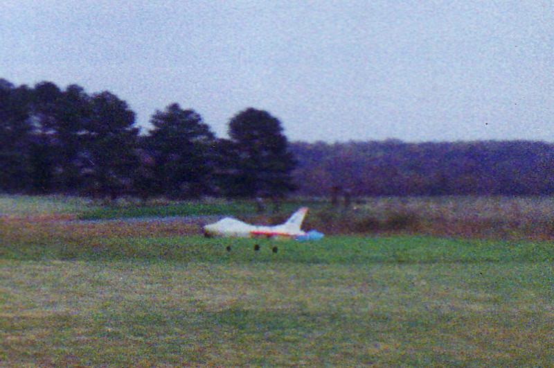
Instead, I was worried that the wing incidence might not have been right, and installed some pattern-style incidence adjusters. The first flight of the prototype was going fine, when suddenly, one of those adjusters came loose, allowing severe wing flutter, and the plane crashed. This was discouraging, of course, but I had flown, and knew that the incidence was right. So, another prototype was built, but this time with the standard wing alignment system, and no paint. (No use wasting all that effort, until I was convinced that all was ok.) The photos below are of prototype #2. Not as pretty, but functional. (Note: Remember, this is the early 1990's. (no digital cameras) The construction photos were shot with a 35mm camera, but that wasn't working during flight tests. So, these photos were shot with a cheap "110" camera, and that's why the quality is lower.)
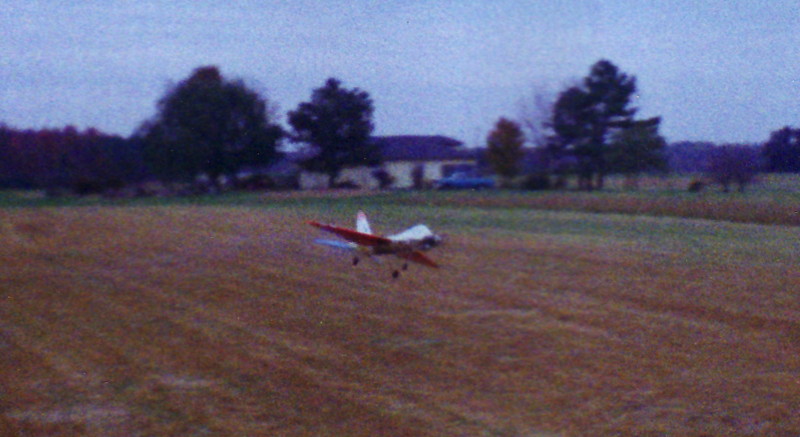
Takeoff
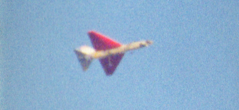
Flight at a safe altitude
A low pass
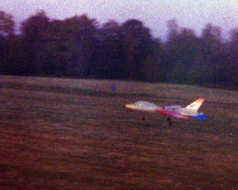
Landing
Looking at the photos above, you can see that at low to medium speed, it's taking a lot of up elevator to maintain level flight. At first, I assumed (as above) that this was an incidence problem. Actually, I found that it was due to a nose heavy condition. That was the biggest lesson learned from this project. I ultimately added several ounces of lead in the tail to get the plane flying properly, but one thing leads to another... Add more weight, and you need more power, etc.. Rather than try to "force' the plane to fly, I abandoned this project, in favor of a smarter design.
If you design practically ANY modern jet fighter to be flown with an engine in the nose, and it's semi-scale or scale, you will ALWAYS have a nose-heavy condition. That's why the successful "sport-type" jet kits don't look scale. The designers have had to move the wings forward, etc., to get the thing to fly right. It probably would've been functional as a pusher-type, but the tail design meant that I would've had to make new plugs and molds, etc.. Too much work for not enough results.
I had been working on a delta-wing version of this kit in the background, and had the prototype done better, might have pursued it. It used the same fuselage, simply removing the tail parts.
The delta-winged "XL" version mockup
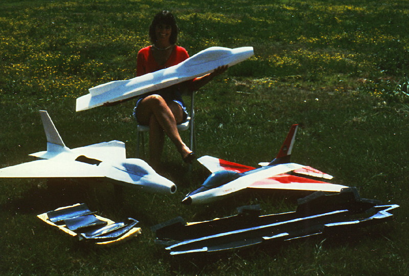
Both prototype planes, and all the molds.
This project ultimately led to the "Eliminator 2". Click here to go to that page.