- Design
- Development
- Simulator Tests
- Construction 01
- Construction 02
- Construction 03
- Construction 04
- Construction 05
- Construction 06
- Construction 07
- Construction 08
- Construction 09
- Construction 10
Testing of the J-47 "Eliminator 2" Sport Jet in "X-Plane"
(For info on the "X-Plane" simulator, click here.)
Construction 00 - Design Overview
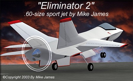
J-47 "Eliminator 2" Sport Jet
Using information gained by another project, "Using a plastic display model to produce RC plans", I've created a sport jet which can be flown with a standard .60-size 2-stroke engine, and a 12" propeller. (I mention the prop size because the landing gear is optimized for a 11-degree angle of attack (AOA) on takeoff and landing, without danger of a prop strike.)
*Note: During the construction process that follows in this article, I've decided not to use the lower ventral fins. Research has showed us that I won't need them, and that was backed up with a flight model created and flown in the "X-Plane" simulator. (Click here for info on "X-Plane".) So, disregard the fact that some of these early images show the ventral fins.
Back in 1994, I finished work on a sport jet kit called the "Eliminator". See the article here. I've learned a lot about design since then, and have updated the concept and named it the "Eliminator 2". It will feature flaps, and retracts, as well as optional leading edge flaps. The model will be 69 inches long, with a 57.5-inch wing span. Initial models will have 927 sq. inches of wing area. With a target weight of 10 pounds or less, this gives a maximum wing loading of 25 oz./sq. ft.. Construction will be a molded composite fuselage, with molded composite wing and tail surfaces. A lot of research and development went into this model. If you'd like to view a brief history of how the model came to be, click here.
Aerobatic and "sport" type planes generally work best when they're kept simple. A Pattern plane is a good example. But...
I like to experiment with technically challenging "gadgets" from time to time, and there are several design goals associated with this project. First, it will have high-lift devices built into the wing, including a fighter-type mixing of trailing edge flaps and a droopable leading edge. It will incorporate some flight control "modes" like modern fighters such as the F/A-22, where several control surfaces move at once, in response to control inputs. (i.e., mixing for roll, using tailplanes and ailerons together, and "ruddervator" coupled to the tailplanes for pitch control) The wings are higher aspect ratio than the F/A-22, and I hope this will help keep the energy up in turns. Slow speed "issues", due to the reduced wing area will be handled by the leading edge flaps, in combination with trailing edge flaps... a BIG camber change. For those not interested in these fairly complex functions, the model is designed to be flown with a simple 4-channel radio optionally, disredarding the flaps and leading edge flaps. I will try some test flights with tailerons only, to see if it can be kept even simpler for those who like it that way.
After a lot of research, I've decided to keep the fuselage chines small and sharp, to aid in forming inward-rotating vortexes over the fuselage at high AOA. This should improve lift, and help keep the airflow attached to the fuselage. The lower surface of the fuselage is one large, smooth curve, with the "jet inlets" being faked graphically. This reduces drag enormously, while retaining the right look for a modern jet. NACA inlets just forward of the engine cowling will direct cooling air to the engine, with it exiting on either side of the spinner. Based on looking at engine RPMs, airfoil data, and low drag, I expect this model to be able to fly at about 125 mph in level flight... somewhat faster in a dive. I'll see...
Thanks to some very good input from several friends who are aerodynamic whizzes, I've improved the design with several features... With leading edge flaps, it should be able to achieve a high AOA. So, to improve stability in this regime, I've added dorsal fins to the vertical fins, and added canted ventral fins to the bottom of the fuselage. The dorsals should help keep the vortex over the fuselage organized, and the ventrals should help low-speed directional stability, as well as helping to prevent an over-rotation. (Like many modern jets, these are mounted so that they offer almost no drag in normal flight, but help push the nose back down when the AOA gets too high.) The fuselage shape itself has it's max width and height (excluding the canopy) coincidental with the projected max thickness point of the main wing, to maximize lift and reduce drag. Proving or disproving all these design concepts is important to me, so I'll be treating it rather seriously, as if it were a scale subject. I'm not just going to "throw it together".

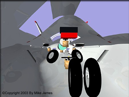
The ventral fins are mounted to give a visual cue when 10 degrees AOA is exceeded on approach.
(At 10 degrees AOA, the bottom edges of the ventral fins are parallel to the ground.)
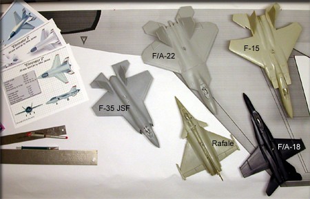
I looked at many modern planforms before deciding on the features I wanted. The design I've ended up with also has similarities to the Mig 29 and the F/A-22. Thanks to stealth and "continuous curvature" technology, shapes are changing.
![]()
The model is designed to be flyable (with fixed landing gear) with 4-channel radios and standard servos.
To allow all the mixing functions I want to try will require 11 servos.
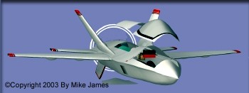
Hatches, gear doors, and canopy will be separate parts.
Plenty of room inside for all the RC gear.
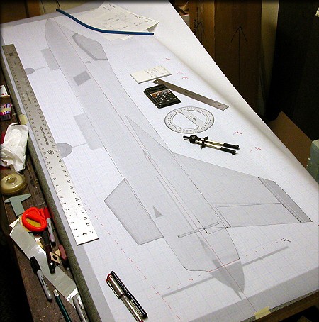
So, after some final tweaks of the CAD model, here I go with the actual-size drawings...
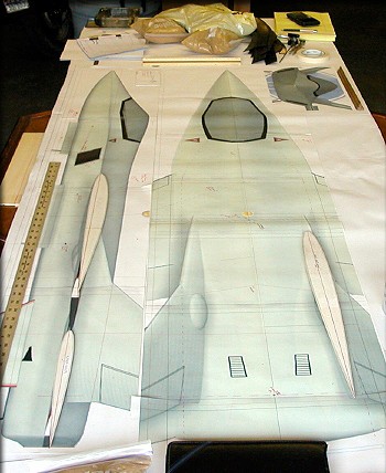
I'm tracing my CAD 3 views onto gridded vellum, and thinking about the internal design now.
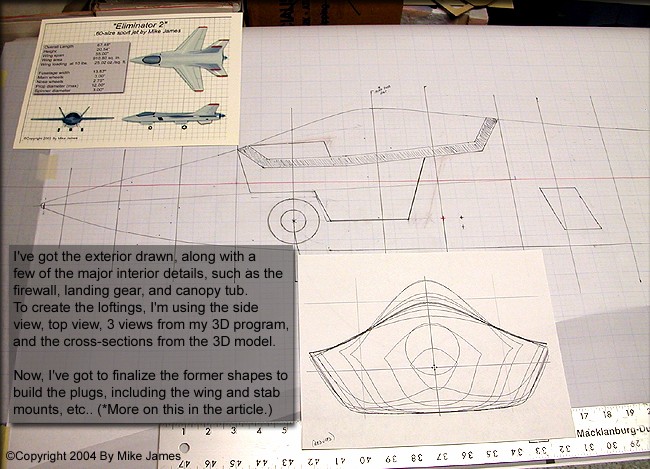
Following the example of full-scale jets of similar type, several things were considered and decided on...
The fuselage max width and max height (excluding the canopy) occurs at the same position as the (projected) max thickness of the main wing airfoil. The idea is to maximize the lifting capacity of the fuselage, and reduce the probability of airlow separation at separate points on the fuselage. If successful, this also reduces drag. Drawing all this would've been tedious with my CAD software, so although the cross-sections you see above are close, they'll have to be refined, according to the drawings, as I go. I'll show more details on this process further along in the article.
There will be molded in root airfoils on the fuselage for the main wing, horizontal stabilizers, and the dorsal fins for the vertical stabilizers. At the end of the process, I'll also mold in alignment marks for the lower fuselage ventral fins.
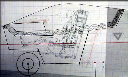
Finally, a "scale" cockpit was considered, because some of us might want to add one later. I made sure that the nose gear strut and wheel well were clear, and outlined (using a scaled "crash dummy" drawing) the cockpit tub to allow for a full-depth ejection seat, pilot, and instrument panel. Judging by these drawings, it looks like 1/8th ot 1/9th parts will look the best. (The pilot shown here (1/9th scale) has no flight gear or helmet, so may look a litle small.) Since the drawing above was done, I've changed the nose gear geometry to place the retracted nose wheel behind the cockpit tub, rather than as shown above.
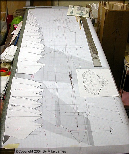
The exterior shape of all the fuselage formers are done, and individual patterns have been made. The next step is to mark some details on them, such as the canopy and cowling separation lines, and attachment points for all the flying surfaces. I'll also be cutting a ("side view") fuselage keel, and creating some precision foam cores, to be used to verify the wing/fuselage blending, during the plug assembly. Several unique features are being built into this aircraft, to make it easy on future builders, and to insure good performance. These will become obvious as the plug construction continues...
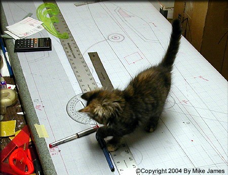
A few landing gear modifications by "Mitzi", and the drawings are nearly complete.
After doing a test print of my 3D files, everything matched with the AutoCad files.
Click the "Construction 01" link below to watch the building process..
>>> Mike James
- Design
- Development
- Simulator Tests
- Construction 01
- Construction 02
- Construction 03
- Construction 04
- Construction 05
- Construction 06
- Construction 07
- Construction 08
- Construction 09
- Construction 10