How to Make Plugs for Molds... Differently
A mold, and the parts you produce from it are only as good as the original plug you make. Besides being accurate to your design, it has to be straight, with all the alignment points perfect, and at the end it has to be polished to a glossy smooth surface. This deserves some thought, since there are a variety of ways to make a plug. If you've seen my Projects page, or the Fiberglassing and Mold Making Techniques page, you've already seen some of the methods that work. I thought I'd share a somewhat more unusual method I used on the 1/6th scale "Avanti", that worked quite well.
The problem with the "Avanti" fuselage plug is that it is HUGE. (Typical cross section of 12 to 13 inches, and 96 inches long!) This meant several things... First, the standard balsa/ply type of structure probably wouldn't work. Not only would it be difficult, if not impossible, to find balsa and (light) plywood in the sizes I needed, but at this scale, it worried me that it might not remain straight, due simply to the weight involved. Also, if I had taken that route, it would've cost me a fortune to sheet and plank the thing, using a forest of balsa and a gallon of glue. So here's what I did instead.
The Keel
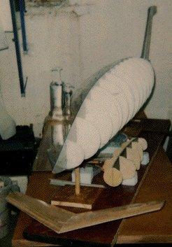
I found a 4 foot by 8 foot section of "Alpolic" at an art supply store. It's composed of an aluminum center with a (black) plastic coating on both sides. I cut out the side view from one set of my plans, which had all the bulkheads and other details marked on it, and glued it to the "Alpolic". Then I got this side view plasma cut locally, and finish sanded all the edges. I knew this assembly was going to get heavy eventually, and would need support, so I took a discarded broomstick handle, waxed it, coated it with PVA, and wrapped fiberglass tape, saturated with epoxy, around most of it's length, in two layers. When this had cured, I sawed the broomstick handle into 4 parts, and pulled off the fiberglass "sockets" I had just made. I mounted two of these sockets (one on each side of the keel) between two of the front formers and two of the rear formers. Then I mounted the four broomstick pieces (each about a foot long) onto a 7 foot long piece of formica-coated countertop, which from then on would be the support for my plug. (At the end, the holes in the bottom of the fuselage for access to the sockets will be filled in and covered up.) Here's a photo of it in use, with the plug further along. The discussion that follows is about how to get to the stage you see in the photo below.
The Formers
Next, I needed about 30 formers...about 15 "half formers" per side. I went dumpster diving at a local art supply store, and found enough discarded plexiglass to last a lifetime, and brought it back to my shop. There, I glued former templates from the plans onto the plexiglass, allowing for the thickness of the keel, cut them out, and carefully sanded them. I cut two formers at a time, stacked, since they had to be symmetrical on each side of the keel. This sounds odd, but we're talking about a plug here, not a flying part. So, within reason, weight was not an issue.
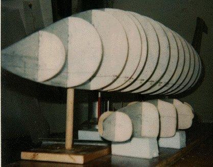
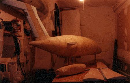
Here are the formers glued to the keel.I left the paper plan sections glued to both the keel and the formers. That's why one side of the model looks "transparent", and the other does not. It isn't obvious in the photos, but I very carefully made sure all formers were "square" to the keel, and used a lot of cut up triangle-shaped pieces to keep them that way, thus avoiding the need for "stringers". You'll see why in the next step. I then followed the same procedure for the engine nacelle, which is the object on the table, beside the fuselage.
The horizontal stabilizer, glassed, is on the table in front of the fuselage, just to show it's size. (29 inches span)
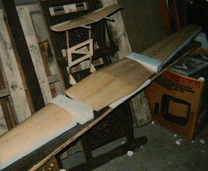
Here are all the wing and stabilizer surfaces sheeted and glassed.
The Shape
Now, with the keel and formers sanded and installed, and everything looking good, I had to come up with a way to create the exterior shape. I could have sheeted the whole thing, but had already decided against that. Another option would be to cut up and place oversize blocks of foam between the formers, then sand them back to the formers. Because this plug was so huge, I decided to do a "science experiment" instead. I went to the local composite supplier and bought a couple of gallons of 2-part liquid, expandable urethane foam. Then I made some temporary "covers" for the bottom 3/4 of the fuselage out of cardboard and aluminum foil. When these were secure, I mixed up the foam and poured it in between the formers, and voila! ... Well, not quite.This worked, but was quite a mess, since some of the liquid leaked out of my makeshift "covers", and some overflowed at the top. (I didn't take photos of that part.)
But the good news is that these errors occur outside of the framework, and have no bearing on the finished plug. Just don't try this in your living room! Anyway. wait a day for everything to cure, and come back with some big sanding tools. From an ugly mess of overflowed foam, I created the shape you see below in about 30 minutes! Now that makes it worthwhile for me! Notice that my work table is covered to about 2 inches depth, in sanded foam. I've found other uses for urethane foam in modeling, including reinforcement of a plastic display model, here, and again, for major parts of the structure of my 1/3rd scale Berkut-Long EZ design, here, and I've used the same technique on the J-47 sport jet, here.
Adding some Finesse
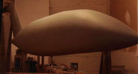
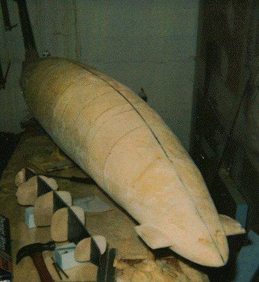
After filling any major "dings", using the same expandable foam, I fiberglassed the entire plug, which takes a LOT of cloth and resin! I used two layers of 6 ounce cloth, and epoxy. The first picture at the top of this page shows the plug after some sanding, in it's first coat of primer. Not bad, when you consider how fast the major portion of the shaping went. I wouldn't use this foam method on an average size model, but for this one, it saved me a ton of time. As long as your plans, keel, and formers are accurate, nothing is lost in the process. Give this a try on your next BIG project!