- Design
- Development
- Simulator Tests
- Construction 01
- Construction 02
- Construction 03
- Construction 04
- Construction 05
- Construction 06
- Construction 07
- Construction 08
- Construction 09
- Construction 10
Construction 01 - Design of the plugs
After printing accurate former patterns, I cut all the parts, making a "kit" for the plugs. In this case, I used 1/8" lite ply for the formers, and used a piece of Masonite™ for the keel and parting board. This assembly is being built on a 1/2" thick piece of tempered glass, after we spent a day insuring that it was flat and level.
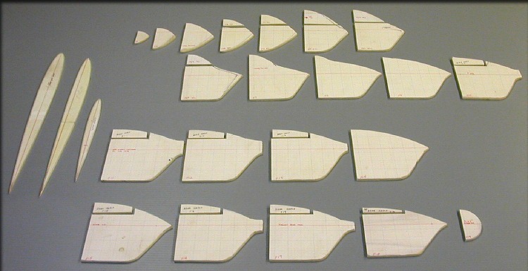
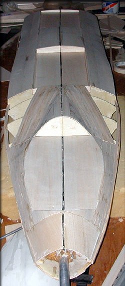
This airplane is non-standard. Specifically, the wing and tail surfaces are blended with the fuselage, as on modern fighter types like the FA-22 and F-35. That being the case, the airfoil roots have to be considered as part of the fuselage sides, and the fuselage itself has to continue (on a swept line, when viewed from the top) in line with the wing and tail thickness ratio. Figuring all this out before cutting the actual parts was a chore, and the design was constantly changed, right up until early August, when these parts were finalized and cut. It's a "science experiment", meaning that if it works as planned, the fuselage will fly neutrally, but assist greatly in lift, especially when the angle of attack is increased. Note the "chine" at the nose, which we hope will create a inward-rotating vortex, helping air to stick to the plane at high angles of attack.
To help builders, I wanted to include nice quality hatches with flanges built into both the fuselage and the hatches themselves. So, you'll notice above that these parts are already separated. The separate canopy and hatch plugs will be attachable to the main plug for shaping, but removable at the end, to make separate molds. So, on with the show...
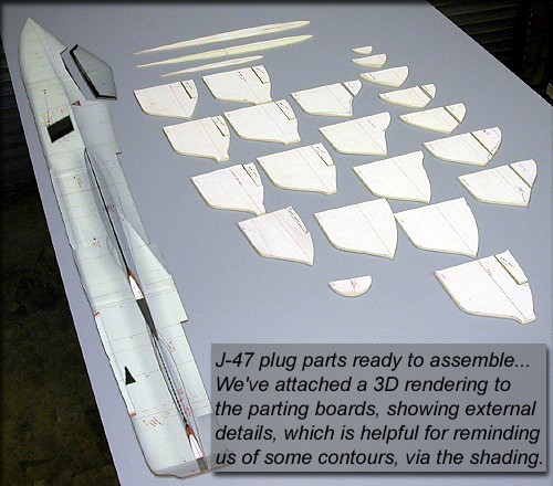
The fuselage and canopy parts on the left are cut out of Masonite™, but I've attached a 3D rendering to it. Having a 2D and 3D reference at the same time is helpful. The parting board needs some finishing work, and is not shown here yet, but is also Masonite™.
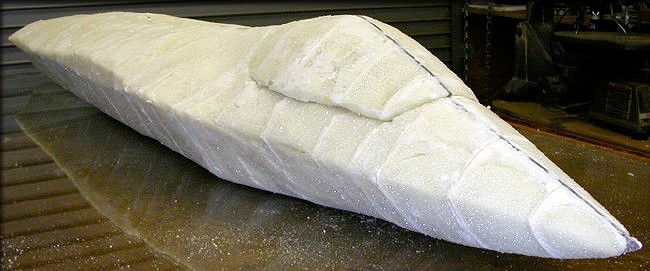
For those of you who've been following along, the original plan was to fill, then glass the assembly here. I've done this on several projects in Alaska, and with good results. (See the constuction of some of the King Air parts, for example.) I should mention that on each of the previous projects, I've always glassed the foam within a day or so.
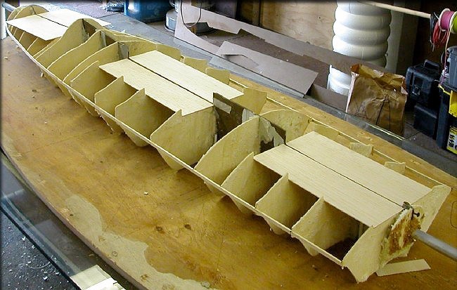
The combination of the temperature and humidity in Charlotte, combined with the fact that this assembly sat for several days before I was ready to seal and glass it, caused it to get way out of whack, alignment-wise. So, rather than plow ahead, I decided to change methods midway through the process. First, I took about 30 minutes to carve all of the foam out of the plug, leaving only the keel and formers.
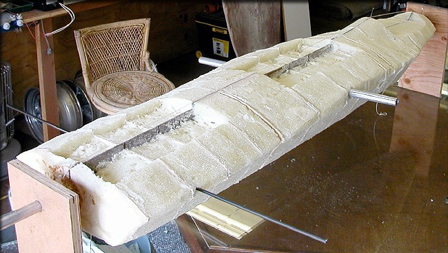
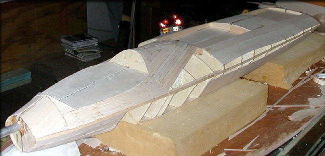
Next, I built the jig below. You can't see it in the photo, but there is a row of pegs in the board below, running the whole length of the model, and that insures that the keel was straight. Then, a combination of stringers and stiffeners was added to further stabilize the plug.
Next, I used a more traditional planking and sheeting method to rebuild the plug, and this time, there are no alignment issues.
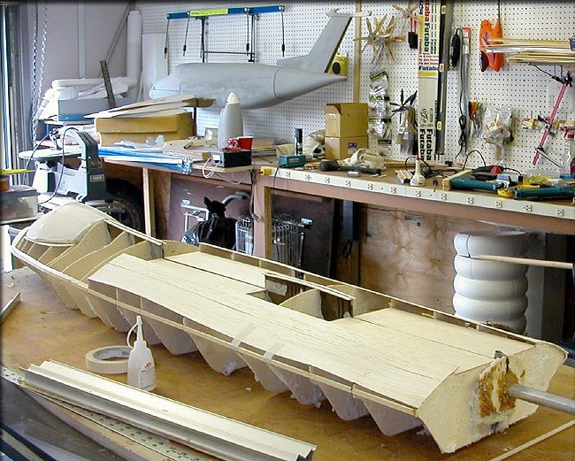
The formers were "CAD perfect", so they didn't need to be redone.
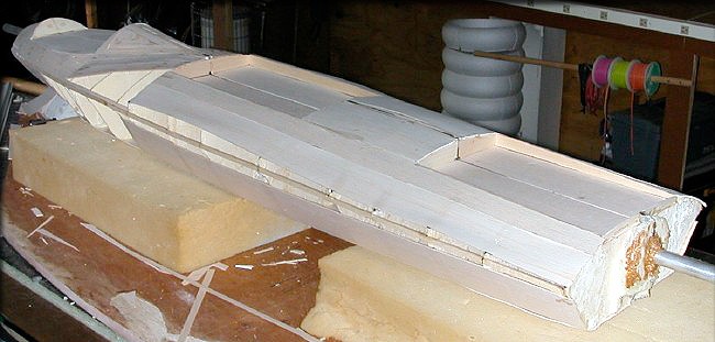
Coming along nicely...The bonus for me is that a wood structure is a LOT easier to shape than what I would've been fighting with the foam surface.
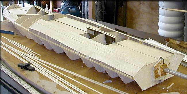
It shouldn't be more than another day or two before this plug is ready to glass.
Saving the wing and tail blending areas for last, but building the canopy deck. etc..
Hatch interiors are also completed.
Canopy deck planked...
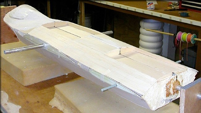
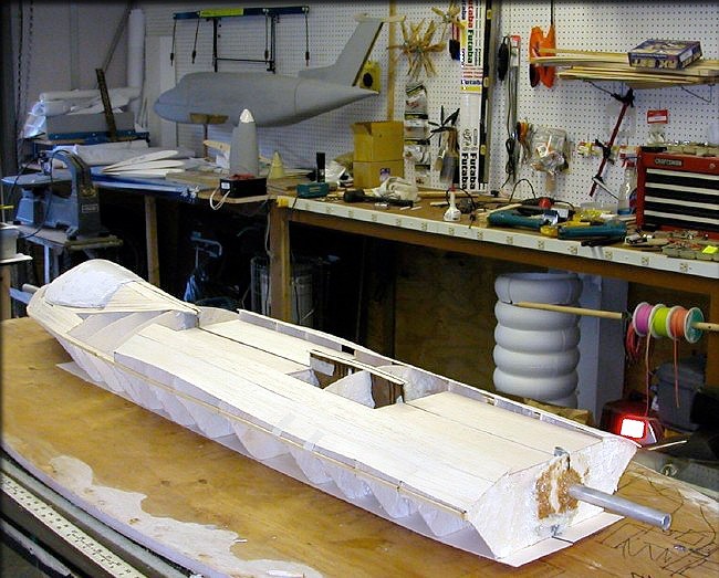
The next step, before glassing the plug, will be to do an alignment check on all flying surfaces.
These are being prepped for that step now. See the next page....
Click the "Construction 02" link below to go the next construction page.
>>> Mike James
- Design
- Development
- Simulator Tests
- Construction 01
- Construction 02
- Construction 03
- Construction 04
- Construction 05
- Construction 06
- Construction 07
- Construction 08
- Construction 09
- Construction 10