- Design
- Development
- Simulator Tests
- Construction 01
- Construction 02
- Construction 03
- Construction 04
- Construction 05
- Construction 06
- Construction 07
- Construction 08
- Construction 09
- Construction 10
Research and Development
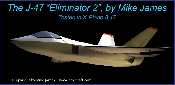
J-47 "Eliminator 2" Sport Jet
For RCers who would like to build something like this, I've created a new variation on this aircraft, called the "J-50", which is now available in my 3D Catalog. By reverse-engineering the 3D model, you could create plans at any scale you like.
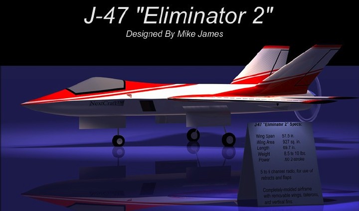
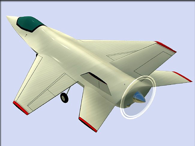
The "Eliminator 2", in it's final form.
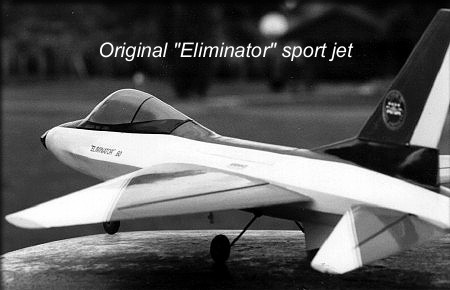
The original F-16-ish J-40 "Eliminator", finished back in 1994.
This design looked good, and it flew, but had problems that made me abandon it. For that story, click here.
In 2003, I decided to do some kind of prop-powered sport jet.. First, I did an online survey on several RC forums, to find out what modelers wanted from a non-ducted fan, non-turbine "sport jet". The results, gathered over the period of a few months, were inconclusive. Modelers almost equally asked for every popular fighter out there.
Take a look at some of the prop-powered sport jet kits that are available today, and you'll see the problem with my original "Eliminator". The main issue, aerodynamically, is that if you use scale proportions, as I did on my first design, the airplane will be nose heavy. You can get around this issue by shortening the nose or moving the wings forward. Those solutions work, but produce an airplane that just doesn't look right to me. I wanted to either produce a scale model, or abandon that idea completely and do something original that looked sleek.
If I were to model a modern fighter, such as the F/A-22, using scale proportions, the airplane would be hopelessly nose heavy with a front-mounted engine. Moving the engine to the rear solves the CG issue, but then the landing gear has to be raised to an odd-looking height to be useable. So, my first instinct was to keep this idea as simple as possible, and basically design a sport plane with a prop up front, and make it look jet-like by simply sweeping the wings and tail surfaces back. The results would've flown ok, (below) but didn't really look much like a jet. I looked at a version with a single vertical fin, and twin vertical fins. Neither was very thrilling.
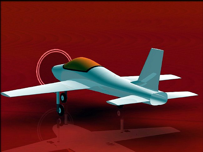
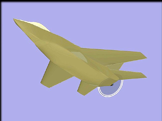
Basically Pattern plane proportions, but with swept wings and tail surfaces... Boring.
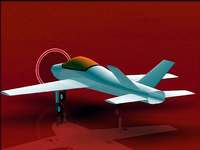
These would've flown well, but just didn't look right. I then abandoned these ideas, and decided to go for more of a scale look.
First CAD models of something vaguely resembling an F/A-22 and/or F-35.
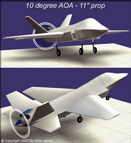
A primary consideration from the start was that the model had to be able to rotate to at least 10 degrees on the ground without a prop strike.
Getting technical and specific about the design goals...
With this being a prop-powered design, power is an issue. Turbine-powered models can make up for drag with raw power, but using a pusher propeller calls for some thought to be given to drag reduction. Low aspect ratio designs, such as the F/A-22, F-15, Eurofighter, Rafale, etc., lose a lot of energy in the turns. Since the whole idea was to end up with a good-performing airplane, I decided on a higher aspect ratio similar to the Russian SU-27. I expect that this will help us keep the energy up in turns better, and also provide better low-speed and glide performance.
At the same time, I became interested in the some of the devices used on modern jets, such as leading edge extensions, fuselage "chines", and the shape of the fuselage itself, as a lifting body. Many model designers write these things off, saying that they can't be effective at the size we build them. I disagree, and set out to prove several things with the fuselage. First, I wanted the fuselage to add something to the overall lift component, but wanted the minimum fuselage drag in level flight, I wanted to prove that at model-size Reynolds numbers, fuselage shapes could be used to help keep the air over the fuselage organized. I consulted aerodynamic whiz friends, including some that had worked on 1/8th scale wind and water tunnel models of the F-18, and studied NASA reports on the (F-18) "HARV" vehicle, etc.. I wanted the model to be stable at high angles of attack and relatively low airspeed, but wanted to reduce the chances of over-rotation. The final issue, that occurs with most swept-wing aircraft, was to reduce the tendency toward "Dutch roll". For both aerodynamic and appearance reasons, I decided on a blended wing-body design. Finally, I decided that the model must be versatile, to allow for the lightest., simplest control method, such as flying with tailerons only, but should also allow for the "gadget-minded" types such as myself, and allow for advanced mixing (like the actual F/A-22 uses) and the use of leading edge flaps.
So, the lifting body concept started to develop, and several things became clear...
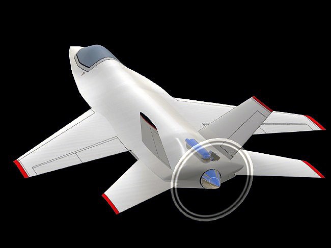
The model was starting to look right, but still needed some finesse.
I studied many modern jet fighters, and even sliced up some plastic display models, to have a look at their cross sections. Doing that showed me that for a fuselage to lift with the wing, the thickness of the fuselage must vary with the thickness of the (blended) wings, and that this varying thickness must follow the same swept line as the mean aerodynamic chord ot the wings. So, excluding the canopy area, that's how the fuselage was designed. The nose area "chine" curves upward from the tip of the nose to the leading edge of the wings, organizing and directing the air, to minimize airflow separation before the air gets to the wings. Continuous curvature allows a gradual pressure increase from the tip of the nose to the leading edges, as the chine goes from almost nothing, to a wider, thicker profile at the leading edge.
Another early decision was to eliminate any sort of jet intakes, since they would only add drag, and not be functional. So, the sides of the fuselage are a continuous curve, from the nose to the tail, and the "intakes" you see are simply painted-on graphics.
The chine has been refined somewhat, but there are still problems at the tail...
The air is prone to separation there, and the engine is sticking up, spoiling the sleek look.
The fuselage was very slightly widened, so that the eingine could be rotated to about 80 degrees, so it could be concealed.
Widening the fuselage had the benefit of increasing the internal space, and increasing the fuselage's lifting area.
Engine cooling must be addressed if you use a pusher configuration. So, there are two flush NACA inlets at the rear of the fuselage, which provide about 6 square inches total of inlet area. This is ducted into the plenum-effect cowling, and exits in three places. There are outlets on each side of the spinner, which gives nearly 10 inches of area, and there's a pressure duct around the internal muffler, which helps cool it, and directs the actual engine exhaust out through a small (3/8") hole in the bottom rear of the fuselage. For engines in the .60 to .90 range, this should be adequate.
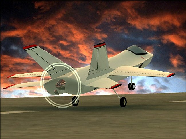
Extended dorsal fins, later extended all the way to the wing's maximum thickness point, help keep the airflow organized at high angles of attack. The image above shows the model at 10 degrees angle of attack, with a 12-inch propeller.
Taking a lesson from the Russian SU-27 and other fighters, the vertical fin's dorsal section was extended further forward. This has several benefits. First, it helps reorganize the airflow to the aft fuselage, just when it would normally be prone to separation. The extended dorsals also aid in directional stability at low airspeed and high angle of attack. The originally-planned F-16-ish ventral fins were abandoned, when I realized that the outward cant of the vertical fins would accomplish the same goal. The increased area provided by twin vertical fins also helps reduce the tendency toward Dutch roll, and since the area exposed to the slipstream is higher at elevated angles of attack, it reduces or eliminates the tendency toward over-rotation.
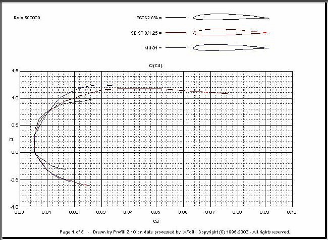
Aided by several friends, research at the expected Reynolds numbers caused me to select the Selig 6062 as the wing airfoil. All of the vertical and horizontal tail parts use the NACA 0006.
Without actual wind tunnel data, estimating the drag of a new design is always a guessing game. We do the best we can, look for published data, and double-check all this with our eyeballs, before finalizing the shapes. Using published propeller nomographs, we could optimistically expect 125 mph in level flight, with a .60-size engine turning a 12-6 (pusher) prop at 12,500 RPM. This matches with several similar platforms that have been tracked on radar. There are some calculations to be done with these numbers, so that at the expected cruise speed, the fuselage is flying at it's "zero" angle of attack, reducing drag. A figure of 85 mph was arbitrarily chosen for this zero degree deck angle, and this let me decide how to mount the wings and tail surfaces on the model. That in turn let me shape the fuselage to blend with the wings and tail surfaces.
Having considered all these things has turned into a real advantage for the design. Aside from the expected performance with a pusher prop, it's also suitable for electric power, and with the addition of proper inlet openings, (simple to add) can be flown as a glow or electric ducted fan design, a turbine-powered model, and even a slope soaring model. We're looking at all of these possibilites, and will let you know when these other variations become available. A flight model was tested in the "X-Plane" simulator, too. See below for a movie, or see all the data, here.
For a movie of the "Eliminator 2" flying, recorded in X-Plane, click the image above. Takeoff from Meigs Field in Chicago, quick climb, some rolls, knife-edge flight, then onto approach, with flaps and leading edge flaps depolyed. (about 16.4 MB)
Many fuselage congurations were tweaked, in the search for the best way to make the plugs and molds.
Most of the fuselage molds I've made have been the traditional left/right type, and so that's what I started with, in CAD. (far left, above) During the plug making process, one of the things that was added was a molded airfoil shape on top of the fuselage, where each vertical fin attaches. Once that was added, it became obvious that the fusealge would have to be molded top/btm, instead of left/right. The bonus of that method is that the mold seam is nearly invisible. It runs along the centerline of the wings and tailerons at the rear, and follows the nose's "chine" at the front. We made the canopy using a bowl-shaped mold, with a lite ply frame to support it, for the same reason. No seams.
Because I expect these aerodynamic things to actually make a difference, it was decided about halfway through the plug making process to mold the entire airframe. That helps keep the airplane consistent, from one builder to another. It also allows us to keep spare wings, tails, etc., in stock, and know that a replacement part you buy will fit and fly as well as the original. Finally, using wing and tail molds allows us to change the internal parts layout and even the skin type, without a redesign. A heavy turbine-powered version, for example, will call for a different internal structure than a electric ducted fan version.
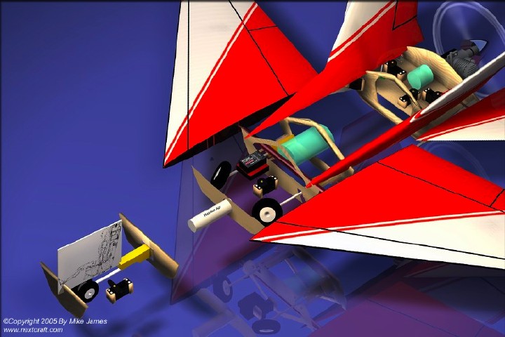
Late in the design process, all the possible interference issues were addressed, and the engine cooling system was refined.
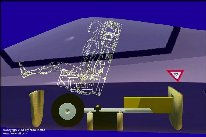
One of the details we paid attention to was the possible addition of a pilot, so internal structures allow for that. (1/9th scale pilot shown)
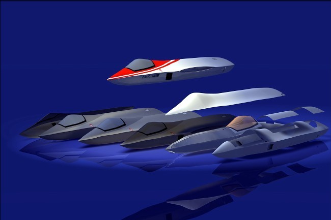
A little fun with CAD...
With all the major issues solved, and the model ready for assembly, I did a little creative image work, which will give you an idea of the various aircraft that influenced this design, and also just have a little fun.
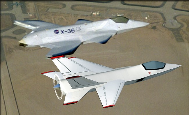
The "Eliminator 2" with NASA's X-36 Tailess Agility Aircraft.
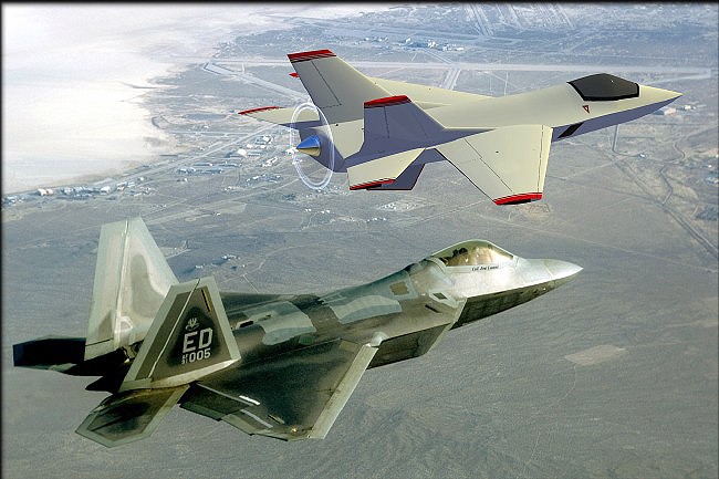
In formation with an F/A-22
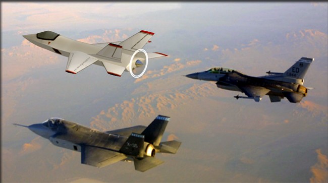
Flying with an F-35 (btm left) and an F-16 (top right)
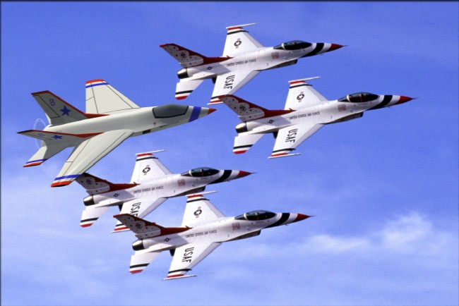
With the USAF Thunderbirds
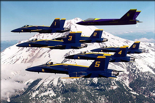
With the NAVY Blue Angels.
Click the "Design Overview" link below to go back to page one of the construction article.
- Design
- Development
- Simulator Tests
- Construction 01
- Construction 02
- Construction 03
- Construction 04
- Construction 05
- Construction 06
- Construction 07
- Construction 08
- Construction 09
- Construction 10