- Design
- Development
- Simulator Tests
- Construction 01
- Construction 02
- Construction 03
- Construction 04
- Construction 05
- Construction 06
- Construction 07
- Construction 08
- Construction 09
- Construction 10
Construction 06 (Final engineering and assembly)
During the early CAD design stage, I worked out the landing gear geometry, including the strut lengths and angles, the gear door lengths, etc.. Still, I have a male plug here, and I'm getting ready to make molds, and I wanted to be absolutely sure that the gear door locations were correct. So...
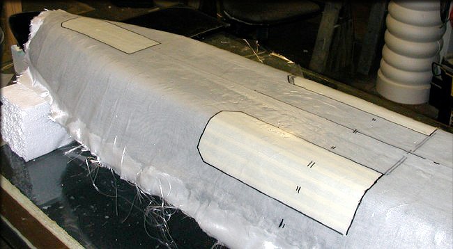
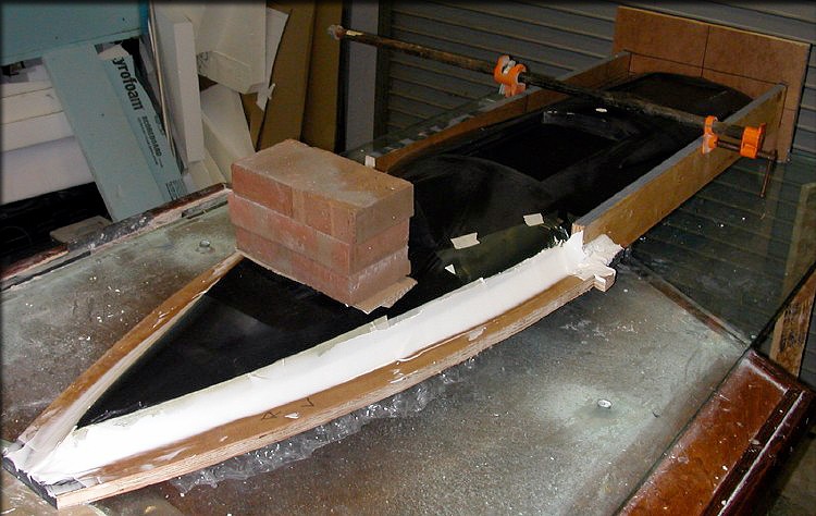
First I placed the fuselage plug upside down on some foam blocks, and covered it with plastic wrap. Next, I did a 2-layer layup of fiberglass over that, and let it cure. It doesn't have to be precise, or even neat, as long as it matches the fuselage plug shape on the bottom and sides. This gives me an accurate representation of the interior of the fuselage, so I could perform the following steps.
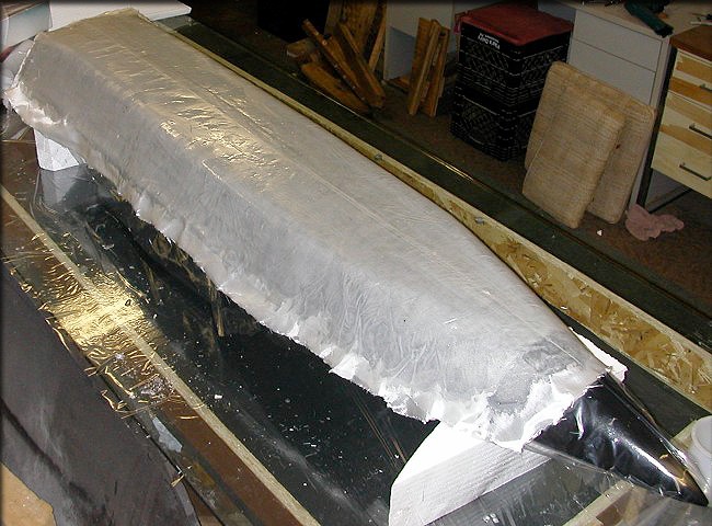
The rough layup on the fuselage, useful in making sure that the gear doors are in the right place.
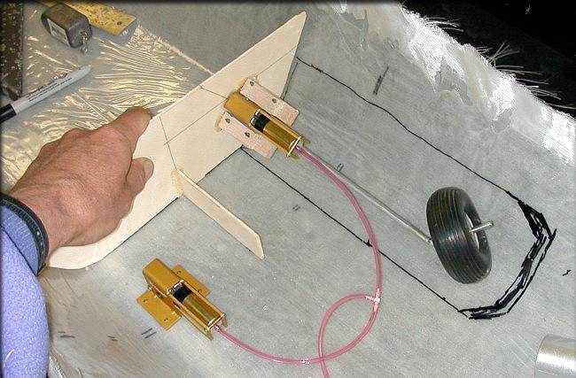
First, using the original CAD former templates, a lite ply former was made to use in this test. The Spring Air retracts are mounted at a 35-degree angle on this former, and set in the "up" position, inside our mockup fuselage shell. I then used a Sharpie to mark out the gear door positions. The next step, not shown here, was to trace the rough gear door outlines, and clean them up, using gridded vellum. Copies were kept to use for the balsa reinforcement patterns that will be used later, and then the vellum copies were taped to the actual fuselage plug, to allow masking.
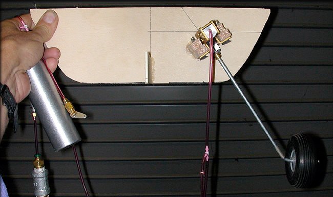
Main gear in the "down" position
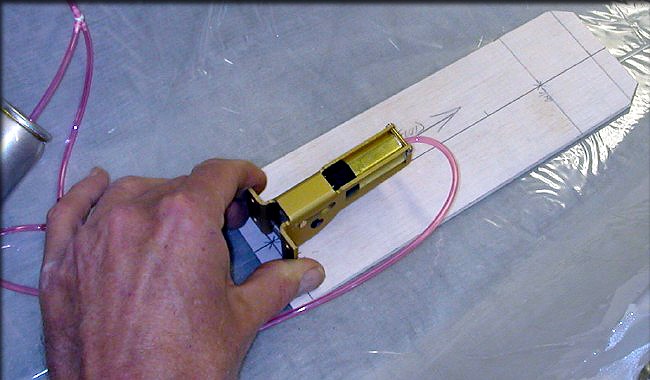
Marking the nose gear door position...Much simpler, since it's right on the fuselage centerline.
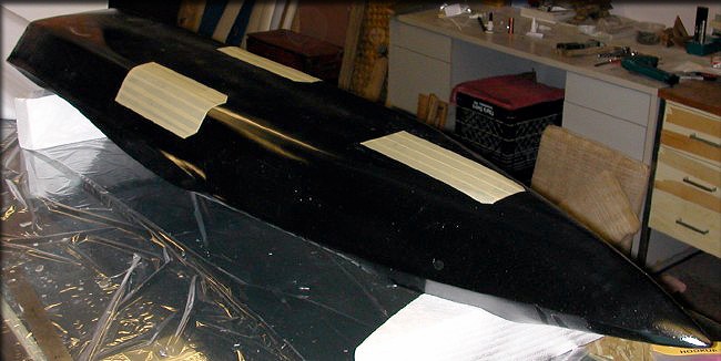
The fuselage plug, masked. I used the paper templates created above, to transfer the gear door outlines to the fuselage, and mask them for painting. This leaves slightly recessed gear door outlines in the plug, which show the builder where to cut, and also will allow us to make female gear door molds, right on the fuselage plug. This all assures a perfect match later, when the doors are installed.
As a final step, the correct door positions were then traced with a Sharpie on the outside of the mockup fuselage, enabling us to cut doors out, and experiment with the hinge geometry, if I choose to. It's also a backup master pattern. After the final coat of gloss black, and buffing, it's time to make the fuselage molds... Can't wait!
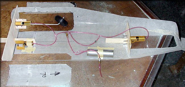
A couple of minutes with some scissors, and the part above was trimmed down to make it more manageable. Once I cut out the doors, I CA'd the mockup formers into place, so I could do some testing on the gear door operation. The obvious advantage of testing like this is that when I install these things on the actual model, the guesswork will be gone.
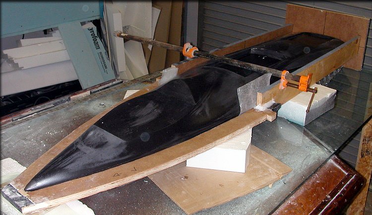
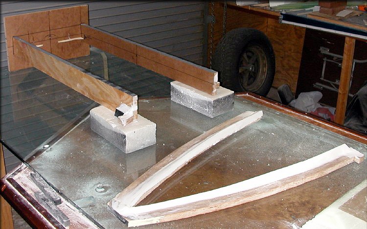
Here's the plug jigged up in the parting board for the first time. The plug has not been waxed or buffed yet, but has been wet sanded.
For a variety of reasons, I decided to make top/bottom molds of this fuselage, rather than typical left/right molds. It will look better, with no seam to hide on the top. It will be easier in production to do the glass layup, and easier to install formers and align them correctly. It does present a problem, which is the downward-curving chine, beginning at the front of the wing, and extending to the tip of the nose. So, the parting board is built in four parts. The rear plate, side plates, and nose section are all separate and removable.
Although not obvious in the photo, because of the black color of the plug, the parting board actually angles downward, below the chine. The edges of the chine were waxed and PVA'd, and then (below) a ridge was built up to the chine, from the parting board. This allows the seam line to curve, following the natural slope of the chine.
The assembly was locked down and secured with weights, so that nothing could shift, while the mixture of epoxy, Cabosil, and microballoons could cure. The next day, the plug was carefully removed, and the built-up ridge was trimmed and sanded, to make a perfect fit with the fuselage.
After curing, the nose section of the parting board has been removed, trimmed and sanded. The nose section is removable, because after the top mold half is finished. it will be removed, while the rear section remains attached. You'll see why, as the molds are made. This is a little different than what i've done in the past, but there are several reasons.
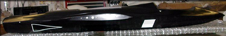
Removal of the tape from all the masked areas on the plug shows the wing/tail alignment marks, intake area, NACA inlets outline, etc.. All these white areas are now slightly recessed, so they'll make obvious painting or cutout areas in the fuselage parts.
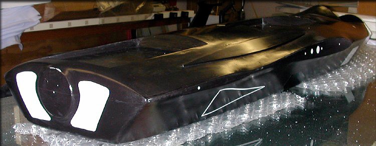
Partway through the waxing/buffing process... You can see the cooling exhaust area here. (NACA inlets give 6 sq. in. of intake, exhaust area is 10 sq. in. through the (plenum) cowling.
Click the "Construction 07" link below to continue.
- Design
- Development
- Simulator Tests
- Construction 01
- Construction 02
- Construction 03
- Construction 04
- Construction 05
- Construction 06
- Construction 07
- Construction 08
- Construction 09
- Construction 10