- Design
- Development
- Simulator Tests
- Construction 01
- Construction 02
- Construction 03
- Construction 04
- Construction 05
- Construction 06
- Construction 07
- Construction 08
- Construction 09
- Construction 10
- Construction 11
Testing of the J-47 "Eliminator 2" Sport Jet in "X-Plane"
(For info on the "X-Plane" simulator, click here.)
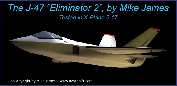
For a movie of the "Eliminator 2" flying, recorded in X-Plane, click the image above.
Takeoff from Meigs Field in Chicago, quick climb, some rolls, knife-edge flight, then onto approach, with flaps and leading edge flaps depolyed. (about 16.4 MB)
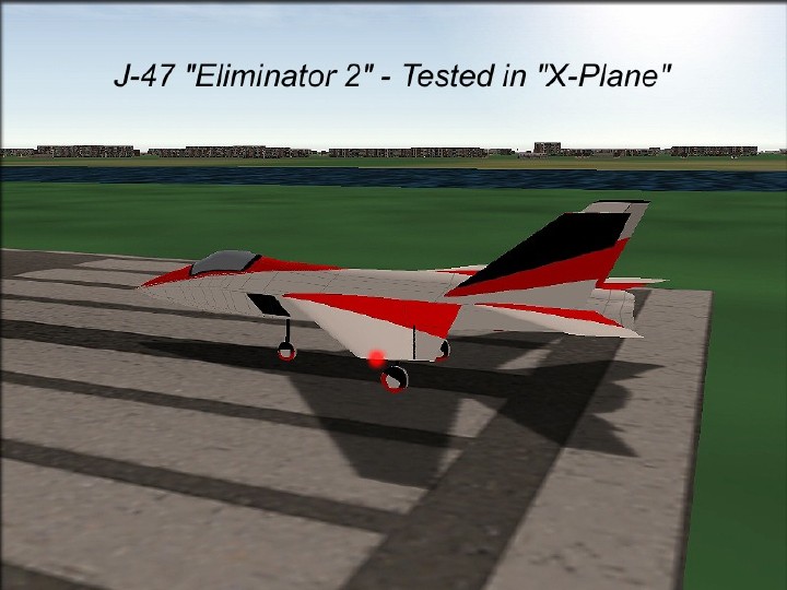
Here are some images from "X-Plane" testing.
You can download the X-Plane version of the "Eliminator 2" here. (free - only tested through X-Plane 8, but should be easy to upgrade in "Plane Maker")
First. a few words about the physical model...
The simulation model was created in January of 2005, long after the design had been finalized, so it was just a matter of collecting all the data I had, and inputting it into X-Plane. X-Plane can do actual RC-sized Reynolds numbers data, but I've found that it's more accurate to use full-scale numbers in this simulator. And, many of the model-specific airfoils we use aren't supported, since x_plane is designed for full-size simulation. Also, I wanted to create this flight model quickly, and like many of my CAD models, tweak the details as we go. It's no rush to have it perfect, as long as the important parameters are right. So here's what I did...
There's a well-done F/A-22 model included with X-Plane, and I used that as a starting point. The "Plane Maker" component of X-Plane lets you load a background image and draw over it, so I used an isometric view of the "Eliminator 2", and first corrected the fuselage. Everything is pretty close, except that I haven't bothered to precisely model the exhaust and spinner yet. This simulation uses a jet engine, which is irrelevant, because except for torque effects, the flying qualities aren't affected. It also gives me the option of testing what turbine-like performance would be like, with a thrust-to-weight ratio greater than 1 to 1. The output model shows me visually when the power goes over 1 to 1, so I know when I'm getting accurate results.
As time goes on, I'll model the vertical fin's extended dorsal fins, but for now, I know they work even without the dorsals, so that's good news. Whatever difference the extended dorsals make will be positive.
I substituted what what I think is an reasonable facsimile of the main wing airfoil, using an NACA 23012, at 0 degrees AOA. The tail surfaces are all NACA 0006, just as they are on the RC model. All of their proportions, locations. deflections, and shapes are the same as the RC model. Landing gear location and CG are also matched to the RC model. Thrust and mass are scaled up, but that's irrelevant for these tests, since we know that the mass will be lower on the model. There is nothing "automatic" or "technical" to enhance the flying qualities... The "auto-stabilization" feature, yaw dampener, and "auto trim elevator pressures" functions were all turned off, and all the testing was done with the only "device" being normal trim controls. The model was refined as much as possible to not require big trim changes.
So you can understand these images...
The "Show flight model" function in X-Plane records all the technical data, moment by moment, and can be captured as a "snapshot" at any time. It has momentum, lift, drag, and velocity data for every component of the plane. Reading a "snapshot" in it's text form is about 30 pages worth... Lots of data.
The visual representation is basically a graph of that same snapshot, with the main feature being the showing of instaneous lift vectors. These are the green lines below. The direction of the line shows the direction of the lift vector, and the height of the line shows the lift vector's amplitude. (The red marker at the end of these vectors is just a visual aid to show the "end" of the vector. The location of the lines themselves shows where the lift vector is theoretically centered. (usually at the 25% chord line)
The yellow lines are the tips of the vertical fin's lift vectors. They extend to show the normal green lines when at higher AOA.
So, these move around in real time as you fly, moving up and down, and changing height. Like NASA graphs of complex systems, it's a great way to absorb what's going on without reading pages of numbers. When I created an X-Plane model of the Berkut, a few years ago, the model performed like the simulation, so naturally I'm hoping that's true here.
Three different versions were tested...
The images below are labeled to show which model is being used, and to keep it easy, the images go in the same order as these models.
Model One was equipped with tailerons only, and included 2 degrees of washout on the wing. (more on the washout issue later)
Model Two used ailerons for roll control, included flaps, and used the tailerons as elevator only.
Model Three is the high performance "gadget" model that I want to build for demos and for my own satisfaction.
I never depend on X-Plane data to totally prove a design. But, it does seem to predict all the important things you would want to know before committing to a design. In the case of the "Eliminator 2", I already did all the math "the old fashioned way", so I can't say I was shocked by the results here. The biggest differences in performance were produced by varying the power. It leads me to believe what we already know. A .60-size engine should power this plane about like a Ramtec .90 powers an Avonds F-15. It will be scale-like, but you will have to wait for the airplane to accelerate, and it won't have raw vertical power. More power makes the airplane a better performer, as expected, and I now am convinced that it would make a nice turbine model.
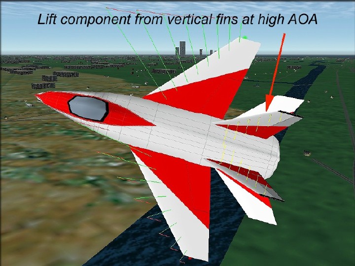
Here's the taileron-only model, being banked and yanked.
Two nice things about this image are the when the lift vectors spike, as they are in this situation, the lift remains concentrated in the center (CG) of the plane, and there's an added vertical lift vector from the vertical fin surfaces. This only happens with the airplane is turned, and the vertical fins are nearly neutral in cruise. As expected, these tend to damp the Dutch roll tendency that all swept-wing airplanes are subject to. Dihedral on all models is zero degrees. The taileron-only model flies as well as the others in normal cruise and maneuvering, but is slower in roll. Since the mass of the RC model is lower, it may not be an issue.
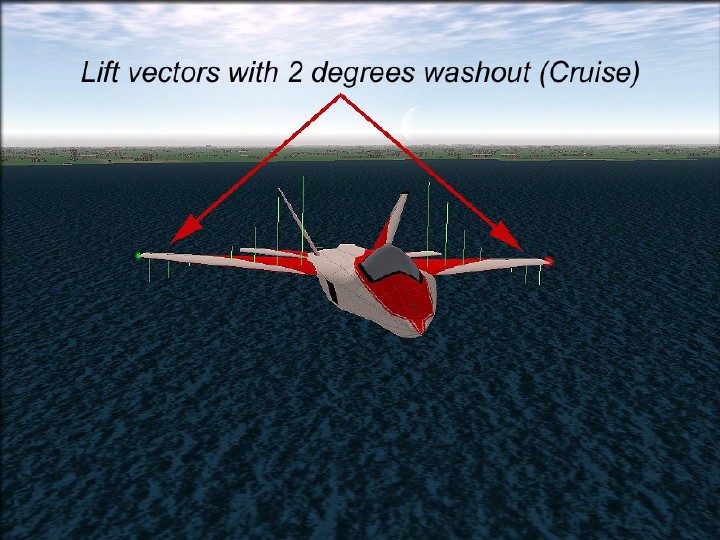
This is what happens to the lift vectors at cruise speed, when there is more than 1 degree of washout in the wings. It's not terrible, but it does contribute to Dutch roll in level flight, so when I made the wing molds, I reduced the washout to 1 degree. The net result is not only less Dutch roll, but also less twisting force on the wing, and more lift overall in nealy an elliptical pattern. (ideal)
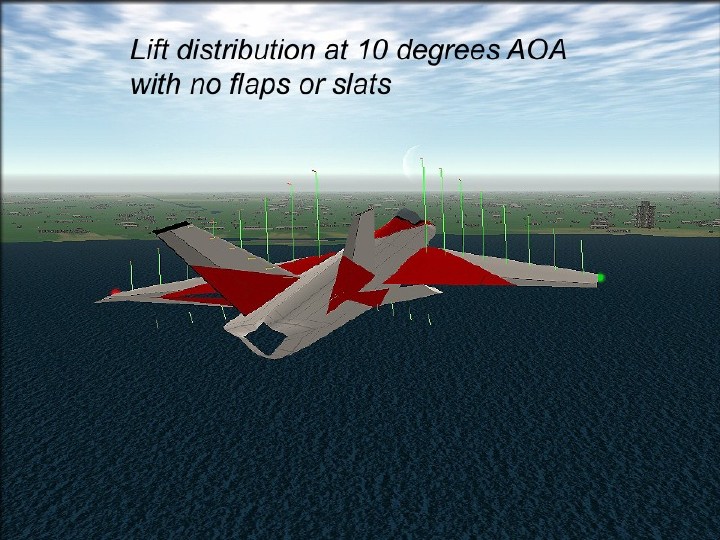
The airplane stays stable in pitch and roll at high AOA. Notice the huge taileron deflection, at 10 degrees AOA and level flight.
Without flaps, this plane is landed at a moderate speed, like you'd expect. Good power management allows the plane to be landed slower, by gradually increasing the AOA. Flap-equipped versions allow the same procedure, but with a lower speed, and more power required to overcome the drag. Glide performance is reasonable for a jet-type model.
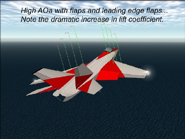
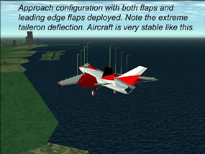
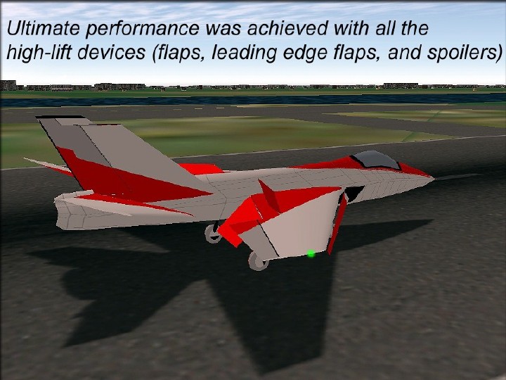
The ultimate performance was achieved with both flaps and leading edge flaps. These alllow the same qualities as above, but with an additional 10 degrees of AOA, which is significant in slowing the plane down, and more power is required on landing approach. In maneuvering flight, the leading edge flaps provide an increased AOA, which is helpful in forcing the wing into it's maximum lift coefficient, especially at low speed, when the tailerons are running out of energy.
With flaps, the model gets a higher inboard spike on the lift vectors, (see above) but also more drag, as expected, for approach.
In this image, leading edge flaps are also deployed, which has moved all the lift vectors forward, and allows a 20 degree AOA, level flight. That's 10 degrees more than with flaps alone, and you can see that it's not requiring a lot of elevator power from the tailerons. Notice that, like a full-scale F-16 or F-18, the tailerons are actually producing an "up" force, (down elevator) to counter the added AOA provided by the leading edge flaps. That's the predicted performance on paper, so it's gratifying to see it predicted here, too.
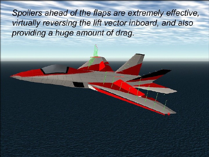
Here's the model with everything deployed...Leading edge flaps, full trailing edge flaps, (40 degrees) and spoilers.
I tested spoilers just in front of the flaps. Wow! The lift vectors are virtually reversed, the instant they're deployed. They're a very fast and effective speed brake, and a great way to get down fast. Aileron control remains positive all the way to the stall.
This model is using a jet engine, so they are no torque effects, and I can't predict a possible torque-induced "break" at the stall. In the simulation, the stall is simply a gradual loss of lift and a pitched-up decent. If the airplane is "yanked" in pitch, at slow speed, it will snap roll, like any plane. In the simulator, the deployment of leading edge flaps prevented this entirely, I definitely want to add these to a personal version, when time permits.
The model is stable in all modes. I can't clearly tell if x_plane predicts "blanketing" of one surface by another, but it does appear to, based on effects on the vertical fins I've seen with the tailerons fully deflected..
If that's the case, then we can probably depend on it that the RC model will perform like the simulation.
Not just eye-candy...
No doubt about it... The best performance was using all the available high-lift devices, especially the leading edge flaps.
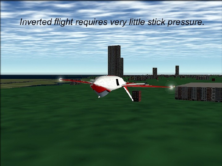
Nearly neutral flight inverted in the simulation. The model was easy to fly inverted.
- Mike James -
- Design
- Development
- Simulator Tests
- Construction 01
- Construction 02
- Construction 03
- Construction 04
- Construction 05
- Construction 06
- Construction 07
- Construction 08
- Construction 09
- Construction 10
- Construction 11